


what are you looking for?
The first step, knowing the customer's load and stroke, allows us to find the minimum servo cylinder model that meets the requirements using the stability curves in the selection brochure.
The second step, based on the customer's operating frequency requirements, calculate the stroke mileage of the ball screw for that model, and calculate the ratio of theoretical mileage to actual mileage to determine if it meets the 5-year service life (under normal operating conditions). If not, a different servo cylinder model needs to be added until the service life meets the requirements.
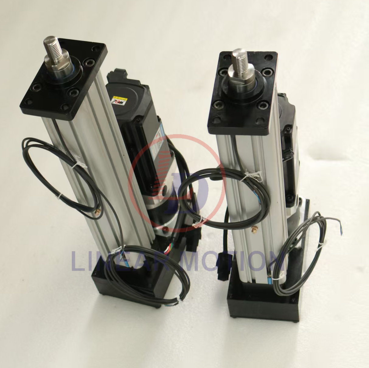
The fourth step, based on the installation type, precision requirements, etc., determines the specific installation type of the servo cylinder and the selection of the ball screw. Servo cylinders come in various mounting configurations, including front flange (FF), rear flange (RF), rear hinge (RC), side trunnion (ST), and side flange (SF). Ball screws are manufactured using rolling and grinding methods; grinding takes longer but yields higher precision.
Finally, the motor type, communication mode, driver type, voltage, and cable length are determined. Accessory structures include magnetic induction limit switches (FCM), proximity limit switches (FCP), dust covers (B), pressure sensors, displacement sensors, and anti-rotation structures. This completes the selection process for a servo cylinder.